Turn-Mill Machining: Turned Parts with Milled Features, Done in One Setup
A turned part with flats, cross-holes or a hex used to need two machines and two setups. Turn-mill does it in one clamping — here is why that holds concentricity better.
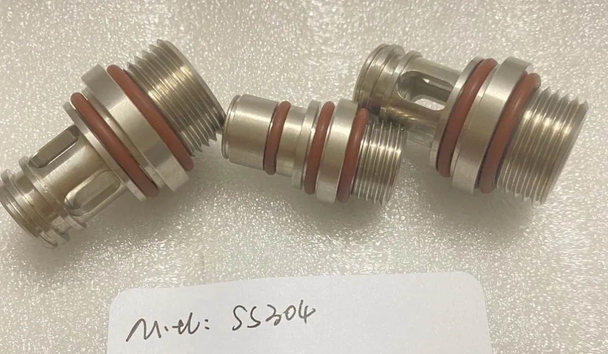
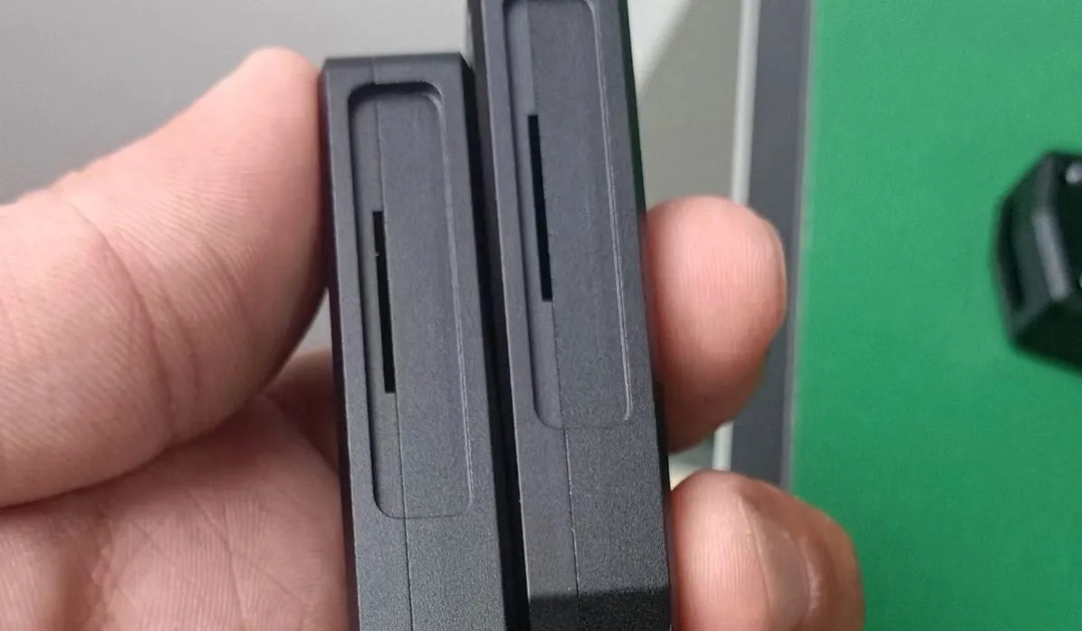
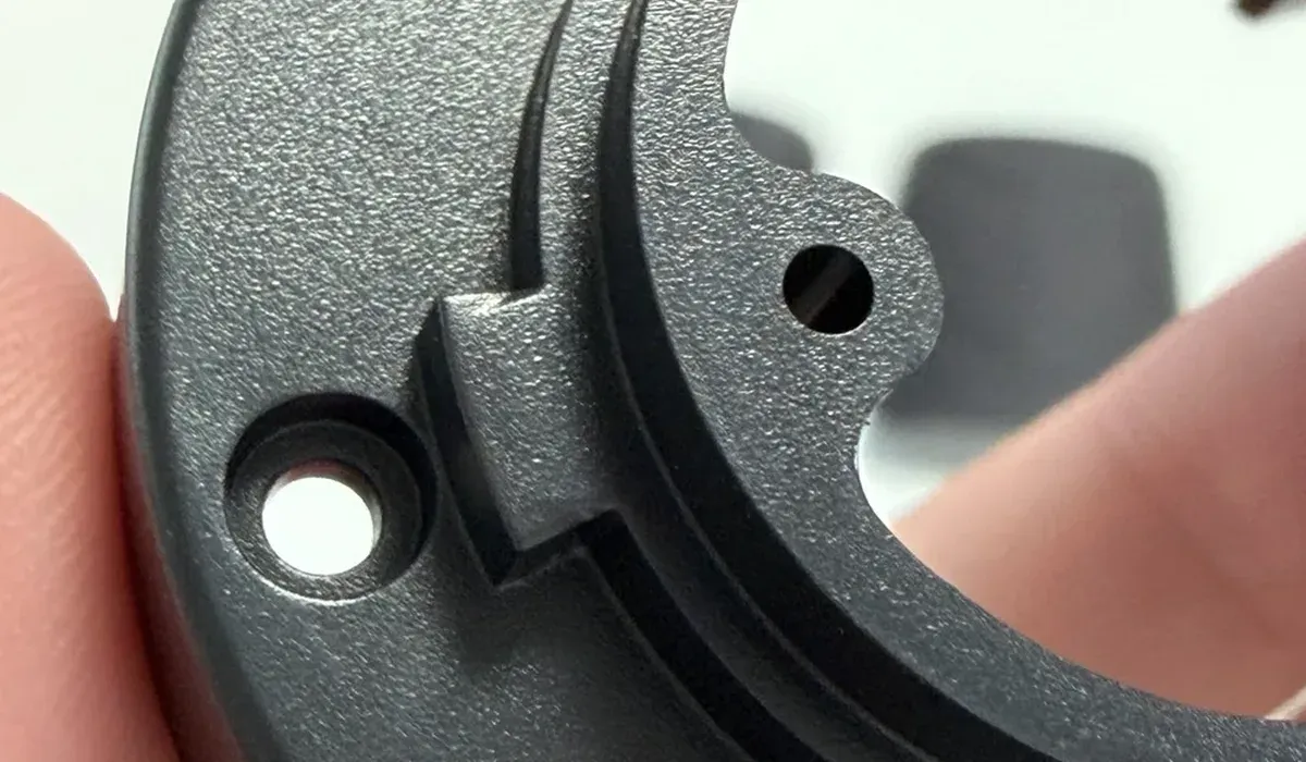
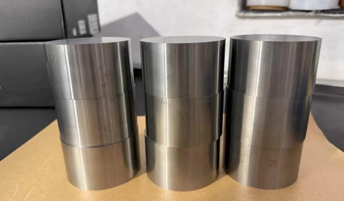
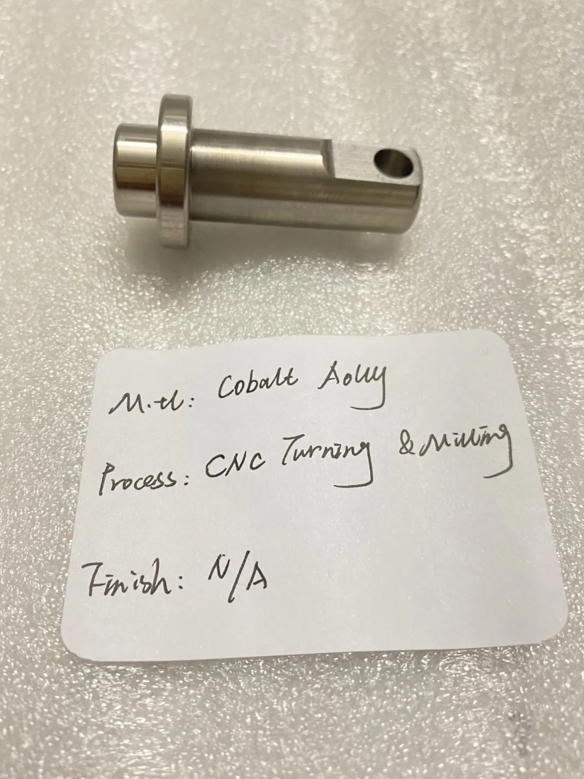
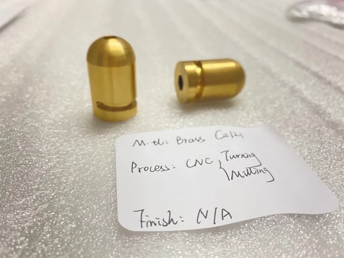
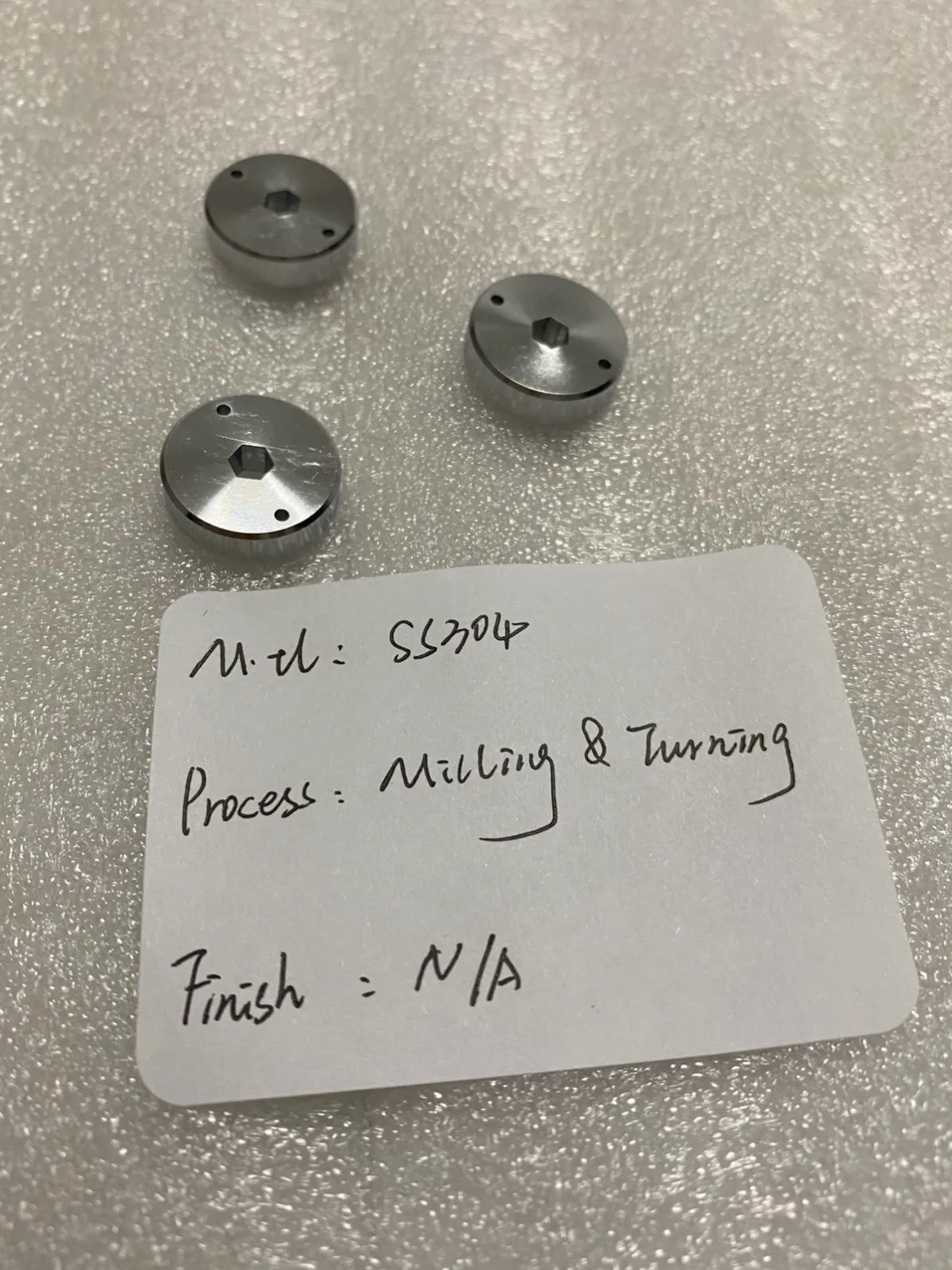
Look at a turned part closely and it often stops being purely turned halfway through the drawing: a flat milled on the shaft, a cross-hole through the flange, a hex in the middle, a slot across the end. Traditionally each of those features meant a second machine and a second setup. Turn-mill machining — a lathe with driven milling tools and a positioning spindle — does the turning and the milling in one clamping. The parts in our photos are all made this way, and the reason is not speed. It is accuracy.
What a turn-mill actually is
A turn-mill center starts as a CNC lathe: the workpiece spins in a chuck and turning tools shape the round features. Added to that are live (driven) tool stations that can drill, mill and tap, and a main spindle that can stop and index to exact angles — the C axis — and in many configurations move the tool sideways across the rotating axis, the Y axis.
That combination covers the features that used to force a second operation:
- Cross-holes and radial holes, drilled at exact angles to each other
- Milled flats, hexes and wrench faces on a turned body
- Keyways, slots and pockets along or across the axis
- Off-center and angled holes in flanges
- Threads milled where a tap cannot go
Why one setup matters: the datum problem
Every time a part leaves a chuck and is clamped again, it is located again — and located slightly differently. On a simple part nobody notices. On a part where a cross-hole must sit at a precise angle to a milled flat, and both must be concentric with the turned bore, the second setup is where the tolerance goes to die.
In one clamping, all of those features are machined relative to the same axis the part was turned on. Concentricity between turned and milled features is then a machine capability rather than an operator achievement, and it repeats across the batch. This is why the cobalt alloy pin in our article on machining cobalt alloys is made in one setup: on hard, expensive material, a lost datum is a scrapped part.
Turn-mill vs lathe-then-mill
The two-step route still has its place — simple milled features on forgiving tolerances, or quantities so large that dedicated fixtures pay off. But for prototypes and small-to-medium batches, one setup usually wins on three counts:
| Turn-mill, one setup | Lathe, then mill | |
|---|---|---|
| Concentricity of milled vs turned features | Set by the machine, repeats across the batch | Set by re-clamping and indicating, varies part to part |
| Handling | One load, one unload | Two queues, two setups, parts wait between operations |
| Lead time | One operation, quoted as one | Two operations, scheduled as two |
| Risk | Datum never leaves the spindle | Each re-clamp is a scrap opportunity |
Turn-mill vs 5-axis: different tools
These two get confused, and they are not substitutes. A 5-axis mill machines a stationary part from many angles — the right tool for sculpted, prismatic geometry (see our 5-axis machining piece). A turn-mill starts from a rotating part: if the part is fundamentally round with milled features added, the turn-mill is faster and holds the round features better. If the part is fundamentally a block with round features added, it belongs on a mill. The drawing usually makes the call obvious.
When a plain lathe is still enough
Plenty of turned parts — shafts, bushings, spacers, simple flanges — have no milled features at all, and they belong on a plain CNC turning setup at plain turning prices. Turn-mill earns its place exactly when the drawing mixes the two families of features. If you are not sure which route your part needs, send it over: the route is chosen in the manufacturability check, and it is priced into the quote either way.
FAQ
What is the difference between turn-mill and a lathe with live tooling? They are the same idea at different levels of capability. "Live tooling" is the driven tool station; a full turn-mill adds the indexing C axis (and often Y axis) that lets those tools work at precise angles and off-center positions — which is where the accuracy benefit comes from.
Does turn-mill cost more than separate turning and milling? The machine hour costs more; the part usually costs less. One setup removes a second machine's setup time, the handling between operations, and the scrap risk of re-clamping. On parts with several milled features, one setup is normally the cheaper total.
What features can be milled on a turned part? Flats, hexes, cross-holes at set angles, keyways, slots, pockets, off-axis and angled holes, and milled threads — in practice, most features that appear on turned-part drawings. Deep prismatic pockets and sculpted surfaces are where a part stops being a turn-mill candidate.
Which materials suit turn-mill work? The same range as our turning and milling generally — aluminum, stainless steels, brass, steel, titanium and hard alloys. The parts in the photos are 304 stainless steel, CZ121 brass and cobalt alloy.
Can turn-mill hold tight concentricity between a bore and a milled feature? Yes — that is its home ground. Because both features are cut in one clamping off the same axis, their relationship is held by the machine rather than by an operator indicating the part in a second setup.
What should I send for a quote? The 3D model (STEP, X_T or IGES) and a 2D drawing with the hole positions, tolerances and thread details. If some features could be made either way, leave them — we will choose the route and flag anything that drives cost.