Machining Optical Mounts and Lens Barrels
Lens barrels and optical mounts machined for concentricity: fine threads, thin walls held round, and matte black anodizing that kills stray light.
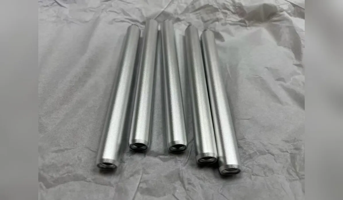
A lens barrel is a tube that has to stay a tube. It looks like one of the simplest parts on a drawing — a cylinder, some threads, a few steps inside — and it concentrates three of the least forgiving problems in machining: everything must be concentric, the threads are fine, and the wall is thin enough to move while you cut it. Optical mounts carry the same problems in bracket form. We machine parts for optics and lens assemblies regularly, and this page explains what decides whether they come out right.
Concentricity is the whole job
An optical element sits in a seat, located by a bore. The thread that retains it, the seat it rests on, and the bore it centers in all have to share one axis, or the element sits tilted and the image tells on it. The machining answer is setup discipline: as many of the critical diameters as possible are cut in a single setup, so they inherit the machine's axis rather than the accumulated error of re-chucking the part. Where a second setup is unavoidable, the part is located off a finished critical diameter, not off a rough surface. Runout and position callouts under ASME Y14.5 are read as specified — and concentricity callouts on older drawings are honored as written — this is the kind of part where GD&T earns its keep, and our tolerances guide covers how we approach callouts like these.
Fine threads, inside and out
Lens assemblies are held together by fine threads — the retaining ring screws into the barrel, the barrel screws into the mount, and the pitches are fine enough that a torn or bell-mouthed thread is a rejected part, not a cosmetic flaw. Fine threads in aluminum demand sharp tooling, controlled depth, and gauging that checks the fit rather than just the major diameter. Thread callouts are made exactly as drawn, metric or imperial, and a thread that must align with a feature (a set screw landing on a flat, a thread starting at a mark) is treated as a timed feature and flagged at quote stage so the requirement is planned, not discovered.
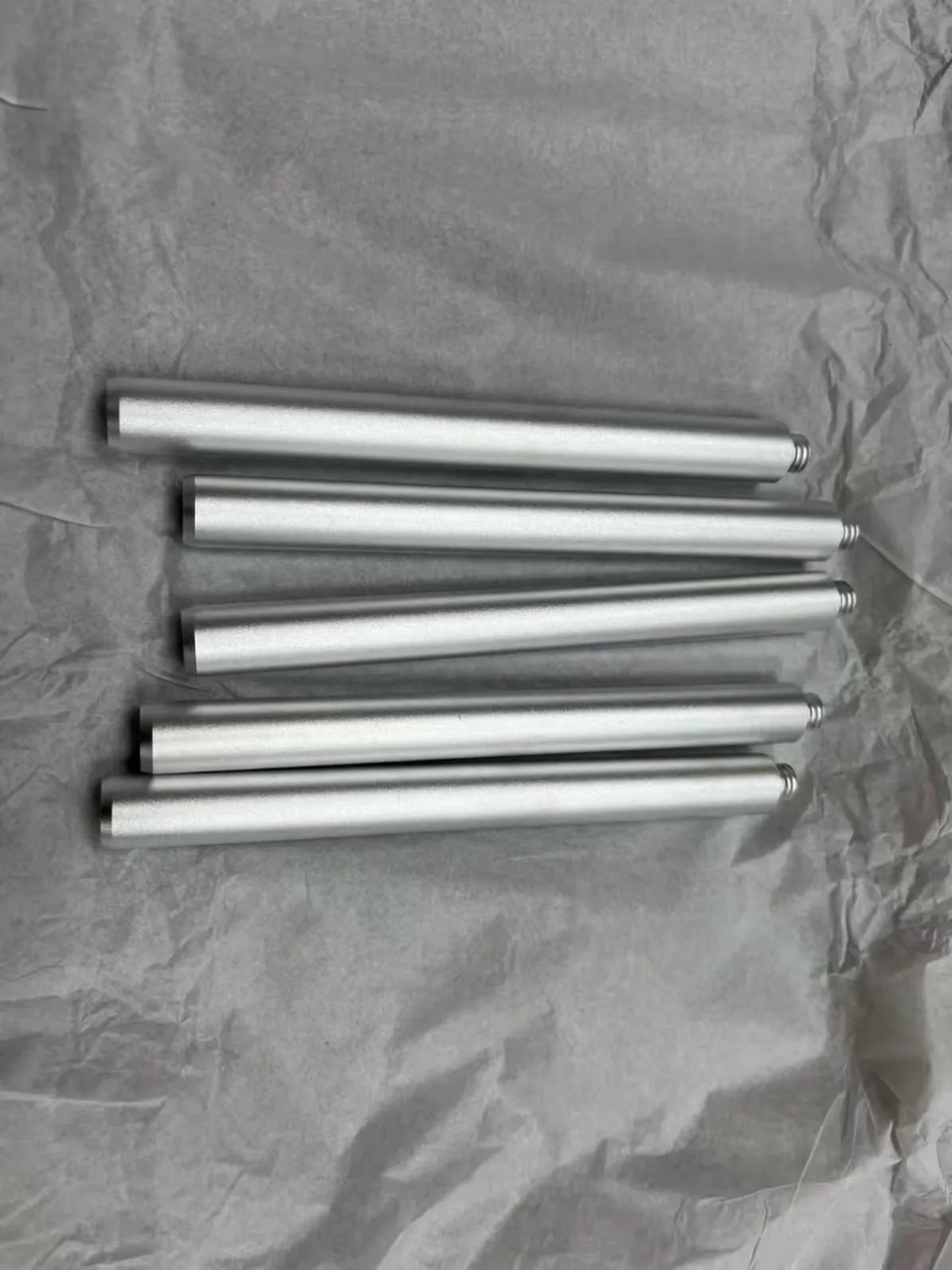
Thin walls move — plan for it
Barrel walls are thin because glass is heavy and nobody wants the metal to add to it. Thin walls deflect under cutting force and under clamping force: squeeze a tube in a chuck and it measures round in the chuck and springs back oval when released. The countermeasures are unglamorous — gentle, distributed clamping, finishing passes with light cuts, and roughing that leaves the wall supported as long as possible. Wall thickness and the roundness you actually need should be on the drawing; where a design is marginal, the manufacturability check says so before quoting, with the wall we would recommend.
Matte black anodizing is a functional finish here
Inside a barrel, the finish is part of the optics. Black anodizing to MIL-PRF-8625 (formerly MIL-A-8625) Type II is standard — it protects the aluminum and, in matte form, suppresses the stray reflections that wash out an image. Bead blasting before anodizing gives the uniform matte surface; the difference between Class 1 and Class 2 and what dye does to the finish is covered in our anodizing specifications guide. Threads and seats are machined with the coating build in mind, so fits finish in tolerance after anodizing, and masking is available where a surface must stay bare — a grounding face or a precision seat. Our piece on black anodized flat parts covers the flatness side of the same finish.
Mounts: the same discipline in bracket form
Optical mounts, mirror holders and lens brackets trade the tube problem for a location problem: two or three faces that must sit in a defined relationship, with holes that line up with the barrel they carry. The approach is the same — critical faces machined in related setups, position tolerances held where the assembly needs them, and ordinary tolerances everywhere else so the part is not priced like a gauge.
Send the drawing through our contact page — the 3D model (STEP, X_T or IGES) and the 2D drawing with thread callouts, concentricity requirements and the finish specified. We respond within 8 hours and normally quote within 24 hours.
FAQ
What tolerances can you hold on a lens barrel? Standard features run to ±0.1 mm (±0.004"); critical diameters, seats and concentricity are held to ±0.01 mm (±0.0004") class tolerances as the drawing specifies. The achievable figure for your geometry is confirmed at quote stage.
Can you machine fine internal threads for retaining rings? Yes — fine metric and imperial threads, internal and external, made and gauged as called out. Timed threads (a thread that must start at a position) should be noted on the drawing and are flagged at quote stage.
How do you stop thin-walled barrels going oval? Distributed, gentle clamping, supported roughing, and light finishing passes — and measuring the part out of the chuck, where it has to be round in service.
Is matte black anodizing available for optical parts? Yes — black anodize to MIL-PRF-8625 (formerly MIL-A-8625) Type II over a bead-blasted matte surface is our standard for optical hardware. Masking is available for seats and grounding surfaces.
Do you machine optical mounts as well as barrels? Yes — mounts, holders and brackets with positioned faces and holes, held to the relationships your assembly needs.