Blog
Sheet Metal Design Tips: Bend Radius, Flanges and Holes
Sheet metal design rules that prevent cracked bends, short flanges and stretched holes: inside bend radius, flange length, hole placement and grain direction.
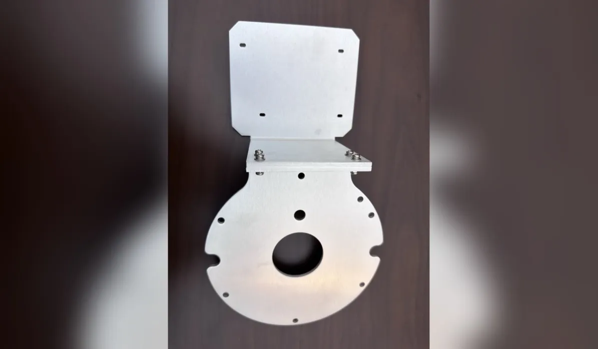
Most sheet metal problems show up at the press brake, not on the screen. A part that looks fine in CAD can crack at a bend, come out with a flange too short to form, or have holes that stretch into ovals. None of these are hard to avoid — they just need to be considered before the flat pattern is cut.
Here are the design rules we check first on every sheet metal fabrication job, and the ones that save the most rework.
Inside Bend Radius: At Least the Sheet Thickness
When sheet metal bends, the outside of the bend stretches and the inside compresses. If the inside radius is too tight for the material, the outside surface cracks — sometimes visibly, sometimes as a weakness that fails later.
A safe rule of thumb: keep the inside bend radius at least equal to the sheet thickness (1 × t). For 2 mm sheet, use a 2 mm inside radius or larger. Softer materials like aluminum in common tempers can sometimes go tighter, and harder materials like stainless steel often want more, but 1 × t is a solid starting point that works for most combinations.
Two more radius habits worth knowing:
- Use the same radius for every bend on the part where you can. Each radius change can mean a tooling change, which adds setup time.
- Bends across the grain are stronger than bends along it. If a tight bend is unavoidable, orienting it across the rolling direction of the sheet reduces cracking risk. If your part is crack-sensitive, mention it and we will watch the blank orientation.
Very large radii are not a problem for strength, but they do change the flat pattern math, so draw the radius you actually want rather than a placeholder.
Flange Length: Give the Brake Something to Hold
A press brake forms a flange by holding the sheet against a die and folding the edge up. If the flange is too short, there is not enough material sitting on the die for the bend to form cleanly — the flange comes out uneven, angled, or not at the dimension drawn.
As a working minimum, a flange should be roughly four times the sheet thickness plus the bend radius. In practice, designers who keep flanges at or above about 10 mm on typical gauges rarely run into trouble. Short flanges are sometimes possible with special tooling, but they are slower and less repeatable, so it is worth asking whether the design can give the flange a few more millimeters.
The same thinking applies to the leg of a channel or the return flange on an enclosure edge: short legs are the ones that cause trouble.
Holes Near Bends Will Distort
A hole punched or laser cut near a bend line sits in material that is about to stretch and compress. When the bend forms, the hole gets pulled — round holes become oval, and the edge distance shrinks on one side.
The standard fix is distance. Keep the edge of a hole at least 2 to 2.5 times the sheet thickness away from the start of the bend radius; more is better for larger holes and tighter radii. The same applies to slots, cutouts, and the edge of the part itself.
If a hole genuinely has to sit close to a bend — a mounting hole that lines up with something, for example — there are workarounds: cutting the hole after bending, or adding a small relief. Both add an operation, so it is a decision to make deliberately rather than discover at inspection.
Also check hole-to-edge distances away from bends. Holes too close to a free edge can bulge the edge during cutting or forming; a couple of thicknesses of material around a hole is a good minimum habit.
Flat Pattern or Finished Drawing: Either Works
Customers ask whether they should send a flat pattern or a finished 3D model. Honestly, either is fine.
Send a finished part model or drawing, and we will develop the flat pattern ourselves, applying bend allowances for our tooling and material. This is usually the safer route, because the flat pattern depends on the exact radius and process used — a pattern developed for one shop's tooling does not always produce the right finished part on another's.
Send a flat pattern you have already proven, and we will cut to it — but tell us it is proven, so we do not "correct" it. If the pattern came from your CAD defaults, say that too; we will check the bend deductions against our process before cutting.
Either way, the finished dimensions are what we inspect against, holding sheet metal tolerances of ±0.1 mm on the features that matter.
A Short Checklist Before You Send the Drawing
- Inside bend radius at least 1 × sheet thickness, same radius throughout where possible
- Flanges long enough to form — around 4 × t plus radius, and not under roughly 10 mm without asking
- Holes and cutouts at least 2–2.5 × t clear of bend lines
- Hole-to-edge distances of at least 2 × t
- Material, thickness, and finish stated on the drawing
- Finished dimensions marked as the inspection reference
Run through that list and most sheet metal parts quote cleanly and run without surprises. If a design cannot meet one of the rules — it happens, especially on compact enclosures — send it anyway and we will tell you what it means for the part before you commit.
For the forming side, see our sheet metal bending services, and for cutting, our laser cutting services. Or send your drawing for a quote — we reply within 8 hours, and quotes are usually back within 24 hours.